Specifications
V7RCDOM‑V2 Specifications
This page continues the story from the homepage and organizes hardware specifications, pin mapping, comparison content, and connector orientation into engineering-focused information.
| 項目 | 內容 |
|---|---|
| MCU | ESP32-C3 |
| Wireless | Wi‑Fi / BLE |
| Size | 31mm × 31mm |
| DC Motor Outputs | Up to 4 channels |
| Servo / GPIO | 4 right-side 2.54 Dupont ports (GND / VCC / GPIO) |
| Power | 3.7V Li-ion battery |
| Charging | Supports external USB 5V charging |
| Programming | USB Type‑C |
| Protection | 1A overload protection on motor output |
| Notes | ESP32-C3 provides only 6 hardware PWM channels, so it can drive up to 6 PWM devices at the same time, such as 4 DC motors + 2 servos |
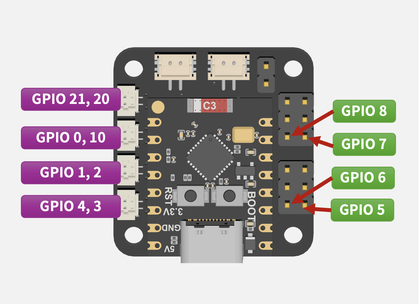
GPIO Connector Orientation
The right-side 2.54 Dupont headers are arranged from top to bottom as GND / VCC / GPIO. A later version can add connector-direction animation and wrong-plug warnings.
Comparison
Specification Comparison
This section is not for vague marketing. It is meant to explain clearly that for small vehicles, educational use, and rapid prototyping, integration means efficiency.
Comparison
V7RCDOM‑V2
Typical Generic Setup
Control Core
ESP32-C3 integrated directly on the product board
A common setup uses a separate MCU board plus extra driver modules
Motor Control
Up to 4 DC motors mapped directly to vehicle use cases
Usually requires an extra H-bridge or dual-channel driver board
Power and Charging
Battery, charging, and power switch managed together
Battery module, charger, and switch are often separate
Pin
Motor 1
GPIO 21 / GPIO 20
Pin
Motor 2
GPIO 0 / GPIO 10
Pin
Motor 3
GPIO 1 / GPIO 2
Pin
Motor 4
GPIO 4 / GPIO 3
Pin
PWM / GPIO
GPIO 5 / 6 / 7 / 8
Pin
Extra Rear Pin
GPIO 9